

HF Digital Messaging - Emergency / Disaster Relief - Interoperative Communications - Ham Radio


| Overview The Micom 2 and Micom 3 series of ALE HF SSB radios are often used in Amateur Radio Service. Here, we provide some helpful guidelines, information, and fill files for various versions and feature sets to enable these fine radios to operate on the ham radio ALE HFN and HFL nets and channels. Please keep in mind, that this page is a work-in-progress, and any of the information or files here are subject to change or inaccuracies. This is not an official Micom site. The information herein is provided for informal educational purposes only. There is no guarantee of any kind that what is provided here is appropriate for the user or for any specific radio model or version. We highly recommend that you seek professional technical service for programming your radio if you are unfamiliar with the complex firmware, software, hardware, and interfacing issues involved. Programming By Computer The Micom 2 and Micom 3 radios are designed to be programmed by a computer before being put into service. Micom radios are available in a variety of software-defined feature sets that are loaded into firmware by a Sales/Service Technician. The channels and ALE features can be programmed by the ham radio operator. It is important to understand the limitations and features available for the radio you are using, before starting to program the channels and features. Two radios may appear the same on the outside, but the firmware inside them is what determines how they will function, and how they can be programmed may be quite different. We recommend the use of a serial port interface cable with a computer using the appropriate Micom MRC programming software, to set up the channels and ALE net programming. Front Panel Keypad Programming Generally speaking, it is complicated (but possible) to set up a Micom for ALE via the front panel by hand jamming the channels and parameters into it via the keypad. The information we provide here about software programming can also be used to program the radio via the keypad, or to change a few of the parameters or channels on the fly. The settings can be seen by opening the *.ale and *.rss files with a browser or notepad text file reader. Fill Files The 2 types of fill files with file extensions *.ale and *.rss are both necessary for programming Micoms for ALE using the MRC software. The rss file should be loaded first and then the ale file. A zip file is also available here for download, it includes both the *.ale and *.rss files. Please note: These fill files are set up for use in USA. The programming can be edited for other countries or purposes. When you use these files, it will over-write the channels and ALE programming in your radio with the new file channels and settings. Please follow the guidelines carefully, do not skip any steps.
 Table of Channels and Nets for Micom MRC HFLINK Fill Files (without Multinet) for USA Download in Excel spreadsheet format HFLINK_MICOM2_2014C.xls Download in comma separated values format HFLINK_MICOM2_2014C.csv PRINTABLE CHANNEL CHART  NETS Configurations for Non-Multinet Radios The purpose of programming these various ALE Net numbers (NET1, NET2, NET3, etc) in Micom 2 radios without Multinet, is to make several configurations of channel scanning and sounding/not-sounding easily available to the operator at the punch of a button. The Net configuration strategy is very different for Micoms that have the Multinet feature. The HFN net (NET 1) is set up to sound and scan on only the Global ALE High Frequency Network (HFN) channels, which are intended primarily for data/text/sounding. The other nets are for combinations of voice and/or text/data. NET 1 is the basic fundamental net used for all ham radio ALE data/text/sounding. NET 2 adds a single 5MHz channel to NET 1, for regional Interoperability use. NET 3 is only the voice SSB channels of the HFL net. NET 4 is a combination of the HFN data/sounding/text net and the HFL voice net. NET 5 is a special net composed only of the USA 5MHz channels. NET 6 is all available ALE ham channels, including 5MHz. NET 7 adds sounding on all available ALE ham channels, including 5357kHz. We recommend NET 1 as the default net for ham operators. For ACTIVE EMCOMM situations, we recommend NET 7 for USA Operators.
Guidelines for Using These Fill Files and Programming With MRC Software (version 1.6) (Note: these guidelines are for programming a radio that does not have Multinet. Some other versions of software or firmware may differ slightly from this procedure.) 1. Connect computer to radio using a programming cable. 2. Connect a dummy load. 3. Turn on radio. 4. Run MRC software. Set up the comm port. 5. Close MRC software. Run MRC software. 6. Top MRC menu: File>Read Device. This loads the programming features into the computer that are already in the radio. 7. Top MRC menu: View/Change>RSS Panel. 8. Top MRC menu: File>Open... > [find and select the HFLINK*.rss file] > Click: Open. 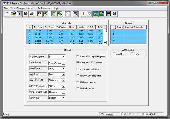 9. The proper Channels and Options parameters should now be loaded and showing in the MRC RSS Panel as shown in the image above. 10. Top MRC menu: View/Change>RSS ALE Panel. 11. Top MRC menu: File>Open... >[find and select the HFLINK *.ale file] > Click: Open. 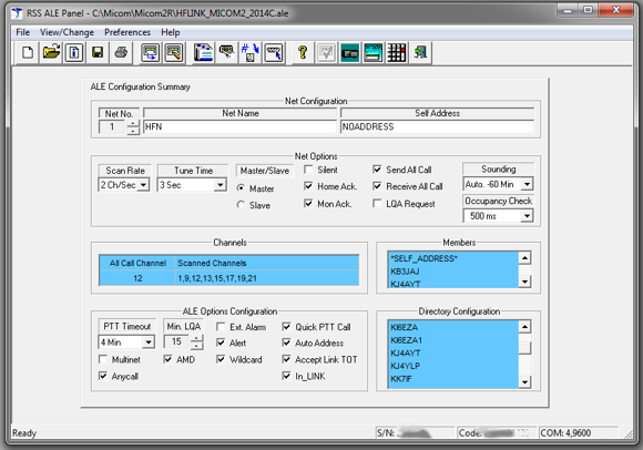 12. The ALE Configuration Summary should now be loaded and showing in the RSS ALE Panel as shown in the image above. 13. Double Click on one of the Addresses (callsigns) in the Directory Configuration. 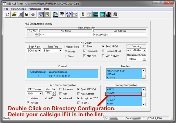 14. Find your callsign in the ALE Directory Configuration. If it is in the directory list: Delete it. Click: OK. (If your callsign is not in the list, Click: Cancel.) 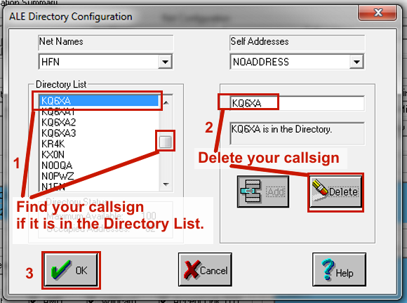 15. In the RSS ALE Panel, in the ALE Configuration Summary: 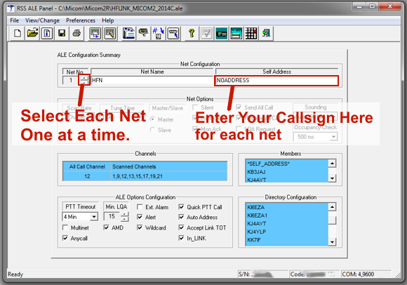 16. In the Net Configuration: in the Self Address: Replace NOADDRESS with your own Callsign. 17. Increment the Net Number on the left side. Enter Your Callsign in the Self Address. 18. Increment the Net Number again. Enter Your Callsign in the Self Address. 19. Repeat step 18 again, selecting each Net, until all the programmed Nets that have Net Names, also have your Callsign as the Self Address. Ignore any nets that do not have Net Names. 20. Important! Double-Check each Net again for your Callsign as the Self Address.  21. Top MRC menu: File>Write Device. 22. Are you sure? Yes. 23. Wait while the programming loads into the radio. The radio will reset. 24. After the radio resets, it will go through a BITE test. 25. Front Panel of Radio: Menu button>SOFT KEY: CHAN> Keypad: 1>Enter button. 26. The radio scanning should now be stopped and channel 1 selected. 27. Use the ^ up button to step through each channel and confirm that the channel frequencies are correct. 28. Front Panel of Radio: Menu Button>SOFT KEY: ALE> Keypad: 1>Enter button. 29. The radio should now be scanning the ALE NET 1. 30. Watch the channels incrementing, and check that these channels are the correct channels for Net 1 (see chart). 31. Front Panel of Radio: Menu button>SOFT KEY: CHAN> Keypad: 1>Enter button. 32. The radio scanning should now be stopped and channel 1 selected. 33. Top MRC menu: File>Read Device. Wait while the software reads the radio program. 34. Top MRC menu: View/Change>RSS Panel. 35. Top MRC menu: File>Save> save the rss file [ your_callsign.rss ] 36. Top MRC menu: View/Change>RSS ALE Panel. 37. Top MRC menu: File>Save> save the ale file [ your_callsign.ale ] Note: These files are your backup programming with your callsign and radio parameters, keep them safe, so you can use them if you ever need to reprogram the radio. 38. Close the MRC program, and disconnect the interface cable from the radio and computer. 39. Front Panel of Radio: Menu Button>SOFT KEY: ALE> Keypad: 1>Enter button. 40. The radio should now be scanning the ALE NET 1. Within about 12 to 20 minutes it should transmit ALE sounds (station ID) on each channel. Check the power output and if possible, verify that there is RF power output. Listen on another receiver to check that ALE signals are being transmitted. 41. If everything appears to be OK, turn off the radio. 42. Connect the radio to a broadband antenna system or autotuner antenna capable of instantaneous good SWR on all the frequencies of the Net. 43. Test the radio on the air with another ALE station, to verify and confirm that your programming is good, and the radio is operating properly. 44. Complete. Guidelines for Using These Fill Files With MRC Software (version x.n) (Note: these guidelines are for programming a radio that has Multinet. Some other versions of software or firmware may differ slightly from this procedure.) 1. Connect computer to radio using a programming cable. 2. Connect a dummy load. 3. Turn on radio. 4. Run MRC software. Set up the comm port. 5. Close MRC software. Run MRC software. 6. Top MRC menu: File>Read Device. This loads the programming features into the computer that are already in the radio. 7. Top MRC menu: View/Change>RSS Panel. 8. Top MRC menu: File>Open... > [find and select the HFLINK*.rss file for use with Multinet] > Click: Open. NOTE: This procedure may be updated at some time in the future to include Multinet programming. How to find the Firmware version of a Micom 2 or Micom 3 radio using the front panel keypad 1. Place the radio in channel mode. 2. Press and hold in the * key. 3. After pressing for approximately 3 seconds, you will see on the display the Software Version (which in this case is more commonly known as the Firmware Version). For example if "RADIO SW V03.5093" and then "DSP SW V00.0267" is displayed, it would mean the radio main Firmware Version is 3.5093 and the radio DSP firmware version is 0.0267 4. If the Firmware Version is not displayed by the keypad method, to find it, you will need to run the Micom MRC/RSS Computer Software and connect a serial cable, as described below: How to find the Firmware version of a MICOM-2B, 2M, 2E and 2ES Series radio using MRC/RSS Software 1. Connect the radio to the computer using the provided RSS cable 2. Open the RSS software and read the radio parameters. (refer to RSS owner’s guide 68P02953C05-O for further assistance) 3. Click on View/Change, and then select “Radio Wide Information”. 4. Repeat step 3 if necessary to see the Radio Wide Information screen. 5. Under the “Radio Model” section, you will see the Software Version. How to find the Firmware version of a Micom-3 series radio using MRC/RSS Software 1. Connect the radio to the computer using the provided RSS cable. 2. Open the MRC RSS software. The software will automatically read the radio parameters. (refer to MRC Owner’s guide 6886869J01 for further assistance) 3. Click on View/Change, and then select “RSS Panel”. 4. Click on View/Change, and then select “Radio Wide Information” 5. Under the “Radio Model” section, you will see the Software Version. Guidelines for Operation on Ham Radio ALE Channels (Note: this space reserved for future updates) Mods Gadgets, D.I.Y., Fixes, Homebrew, and Hidden Features Balanced Audio Computer Interface For Micom (Audio and Hardware PTT) This interface provides balanced, differential, DC-blocked audio connections This is not a Micom product, it is a plan to build a generic interface. 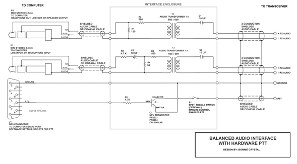 Schematic of a Balanced Audio Interface with Hardware PTT This is not a Micom product, it is a plan to build a generic interface. Micom2 Micom3 Accessory Connector Interface 44 pin This is not a Micom product, it is a plan to build a generic interface. 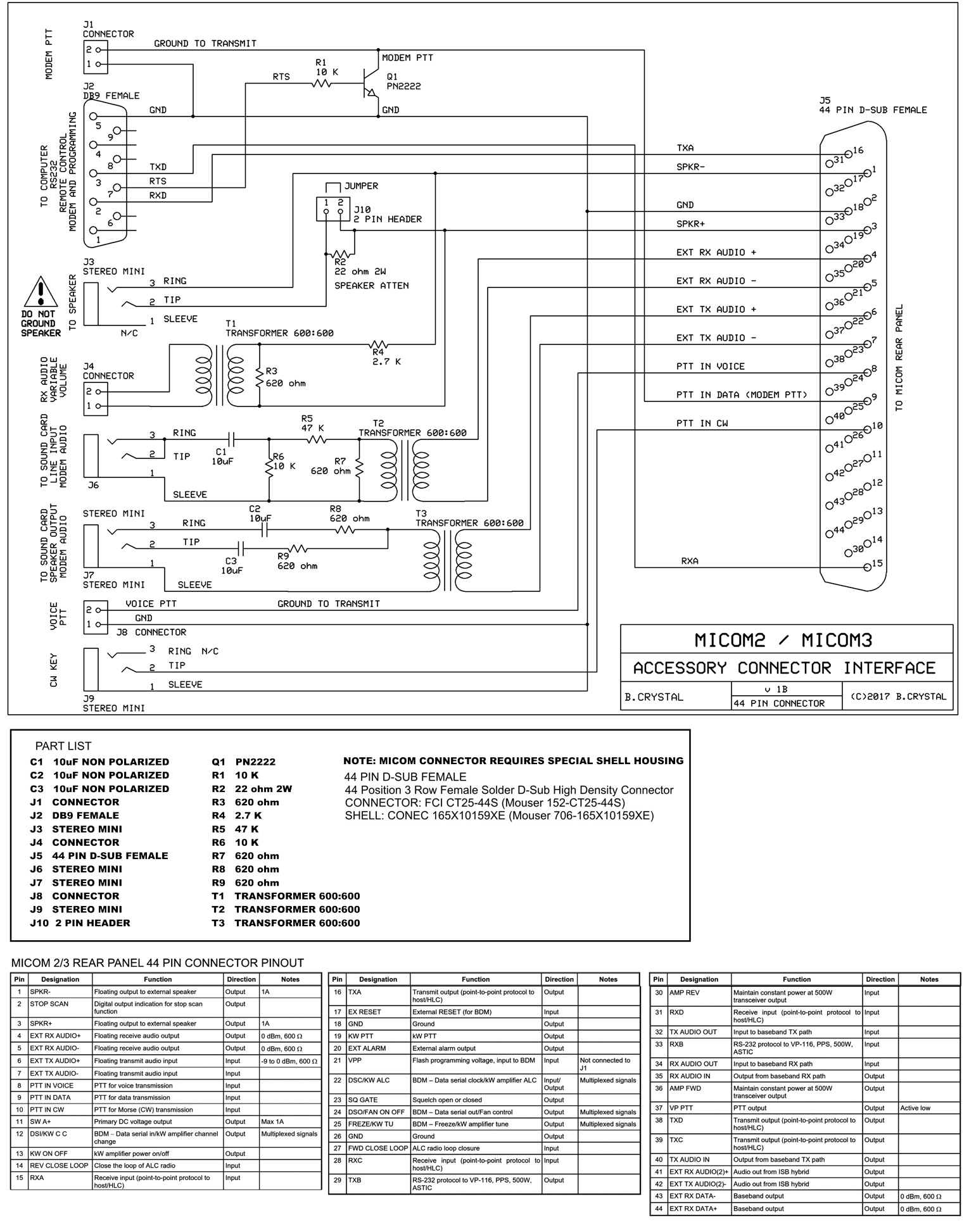 Astatic RD104E Microphone on Micom2R by Bonnie Crystal KQ6XA This is a about my quest for increased "talk power" and better SSB transmit DX audio response for my Micom-2RS (ruggedized version of the Micom 2 series ALE transceiver).  TRIAL AND ERROR WITH H-250 HANDSET, ETC The 2RS requires a microphone with a U-229 connector. The U-229 is the common military type, weatherproof. I've heard that the stock Micom microphone is good. But, I don't have a stock Micom mic, so I've been using an H-250 handset or an M-80 microphone instead. Out of the five good H-250s I culled from a batch of 20 of these handsets accumulated over the years, only one had fairly decent sound. Using the Micom-2RS on a dummy load, I monitored my transmit audio with headphones using another radio with its antenna disconnected. FEEBLE AUDIO Still, the transmit audio has been somewhat feeble for me, using these military microphones. On-the-air TX audio reports were not very good. To get enough drive for the transmitter, the mil mic or mil handset requires close-talking, but then P-pops and breath sounds pulse pump down the transmit ALC in the midst of syllables, causing a muddy or muffled voice quality. Even when talking across the mic, it results in overall inconsistent voice power and lower levels of average transmit power (monitoring on external watt meters and scope). MOTIVATION In preparation for an upcoming HF mobile trip with the Micom-2RS, I decided to finally do something about my microphone situation. I really didn't want to go on yet another road trip without a good mic. SOLUTION: ASTATIC RD104E MIC My solution was to put a U-229 connector on an Astatic RD104E hand microphone. This microphone has an internal adjustable pre-amp with equalization boost in the high end voice range 2200 ~ 3500 Hz. Like the old famous Astatic D-104 microphone, this modern hand mic version is known for its distinctive "crisp" and "clear" sound. The response is similar to the Heil "DX Element" microphone. The acoustic design is noise-cancelling (although my vehicle isn't a high noise environment). There are a few different versions of this mic, but the one I purchased recently for about $40 is aimed at the CB market with the name "Road Devil", and it is red/black in color. I would have preferred the all-black model, but I couldn't find one in stock. The result is a powerful voice signal that cuts through noise like adding another +10dB of power.  Photo of Micom-2RS with
Astatic RD104E microphone
 CONNECTORIZING The coiled cord of the RD104E is a smaller diameter than the cord of an H-250 handset or M80 microphone, so I needed to cut a 2-inch piece of the sheath off an H-250 cord and slip it over the new cord. This turned out to be an exact fit for the combination; it provides a good strain relief and seal for the U-229 connector when it is fitted and soldered. 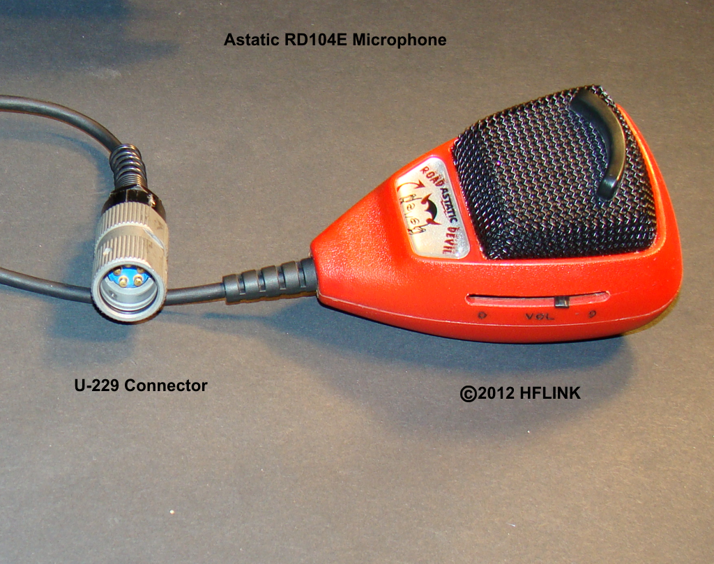 Photo of Astatic RD104E
Microphone with U-229 connector:
FINAL RESULT With the new microphone on the Micom-2RS, my transmit audio is loud and clear. I can adjust the transmit gain using the slider on the side of the microphone, to achieve just the right level of drive for the transmitter. There is no longer any P-pop or pumping of the transmit ALC. The average transmit power on the wattmeter has tripled. I'm ready to take this out on the road now... I will bring along my H-250 as well, and perhaps we can do some A/B comparisons on the air... Audio recording A/B Test of the Astatic RD104E microphone -vs- the H-250 handset Listen to the comparison audio, click here: Test conditions: On the air. Approximately +6dB to +18dB SNR with daylight background static TRANSMITTER: Micom-2RS. Antenna: Dummy load. Test freq: 3996.0 kHz USB Close-talking on both microphones RECEIVER: Yaesu FT-897D. Antenna: broadband vertaloop. Slow AGC, No DSP, Center passband tuning. Background noise level ~S7 static. Received Signal level approx S8 to S9. Audio path: rear panel RX line-out to computer line-in. Interface: Rigblaster Plug and Play A Power Supply Glitch Filter for Micoms by Bonnie Crystal KQ6XA I had a problem with my Micom2RS, it would restart when transmitting, if I powered it with my Alinco DM-330MV switching power supply. This supply is rated at 32Amps. However, when the Micom2RS transmits on ALE on some bands, or if there is microphone audio during the initial PTT instant, then the power supply would see a glitch that would bring the DC voltage down to about 8VDC for less than a half second. This glitch is enough to cause the transceiver to reset. This is a common problem with various power supplies (such as Astron) and has been noted by others. 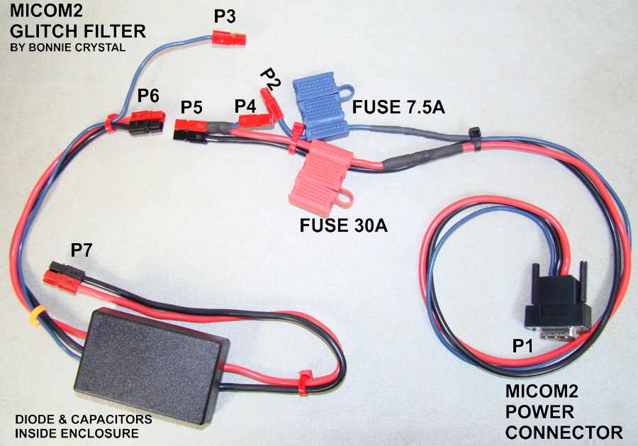 Micom
Glitch Filter
 Micom
Glitch Filter
I
solved the problem by making an external filter box
inserted in the DC power line between the
power
supply and the transceiver. I added a
high
power Schottky diode in series with the
blue
+ DC power line, and 30,000 microFarads of
capacitors to
filter it after the Schottky.
The
+Red and -Black power lines go straight
through
the box without filter or diode.
 Micom
Glitch Filter Schematic
Sending AMD Messages to the Micom STAK ALE AMD RULE: To guarantee that your AMD text message appears in the destination radio's STAK (incoming AMD message inbox), you must send the message as part of the initial link with that station. If you send an AMD texting message while In-Link (after you have already called and are linked) then your text message will appear on the other stations screen, but won't necessarily be saved in their STAK. Notes for Users of PCALE and MARSALE sending AMDs to Micoms: For users of PCALE or MARSALE who want to send an AMD text message to a station who has a hardware ALE radio (such as Micom 2 or Micom 3), when that operator is not at the radio. The operator will be able to read the text later when they check their radio's message in-box (stack or STAK). In order to store an incoming AMD text message, some radios such as Micom, Rockwell, Harris, Icom, and Kenwood may require that the AMD message be delivered during the initial link (rather than while In Link). *Note, these techniques are different than how most PCALE users normally do AMD texting* METHOD #1 : SCANNING AMD MESSAGE 1. Start by not being linked with any station. 2. Scan with PCALE. 3. Press the Green Telephone. 4. Pull down and select the callsign (Address) you want to call. 5. Select the TIS [x] check box. 6. Enter the AMD message text you wish to send. 7. Press OK and Wait. This may take between 1 and 10 minutes. 8. PCALE will step through the channels and attempt to link and deliver the message automatically. 9. After the message is delivered, press Clear Link. 10. If the message fails, go to step #1 and try again. METHOD #2 : SINGLE CHANNEL AMD MESSAGE 1. Start by not being linked with any station. 2. Press the [>] button to select the desired channel for the call. 3. Press the Green Telephone. 4. Pull down and select the callsign (Address) you want to call. 5. Select the TIS [x] check box. 6. Enter the AMD message text you wish to send. 7. Press OK and Wait while PCALE transmits. 8. PCALE will attempt to link and deliver the message automatically. 9. After the message is delivered, press Clear Link. 10. If the message fails, go to step #1 and try again. |
|||||||||||||||||||||||||||||||||||||||||||||||||||||||||||||||||||||||||||||||||||||||||||||||||||||||||||||||||||||||||||||||||||||||||||||||||||||||||||||||||||||||||||||||||||||||||||||||||||||||||||||||||||||||||||||||||||||||||||||||||||||||||||||||||||||||||||||||||||||||||||||||||||||||||||||||||||||||||||||||||||||||


END OF PAGE
©2015~2000 HFLINK. All Rights Reserved.
HFLINK, HF-LINK, HF LINK, and the HFLINK Logo are trademarks of HFpack Inc. Any external hyperlinks must only be to the main page of the HFLINK.COM website http://hflink.com . Capture of the HFLINK website or any part of it within the frame of another website is not permitted. HFLINK group forum is a private group. Public archiving, forwarding, or open display on the internet of HFLINK group forum or messages is forbidden. All text and images on the HFLINK website are property or copyright HFpack Inc, or when used by permission, are copyright by their respective owners, with all rights reserved.
HFN and High Frequency Network are service marks and trademarks of HFpack, Inc. HFLINK is a division of HFpack, Inc. No part of the HFLINK website or HFLINK Group Forum may be used or copied without written permission of HFpack Inc.


